Cells, electrodes, and electrolytes in flow systems
Autor:
Prof. Ernest Beinrohr,
CEO, ISTRAN, Ltd., Bratislava, Slovakia
Cells
In flow systems, particularly in industrial applications, electrodes and electrochemical cells are subject to specific, and often more stringent requirements than conventional arrangements based on an electrolytic vessel with immersed electrodes, a stirrer, and a gas-bubbling system.
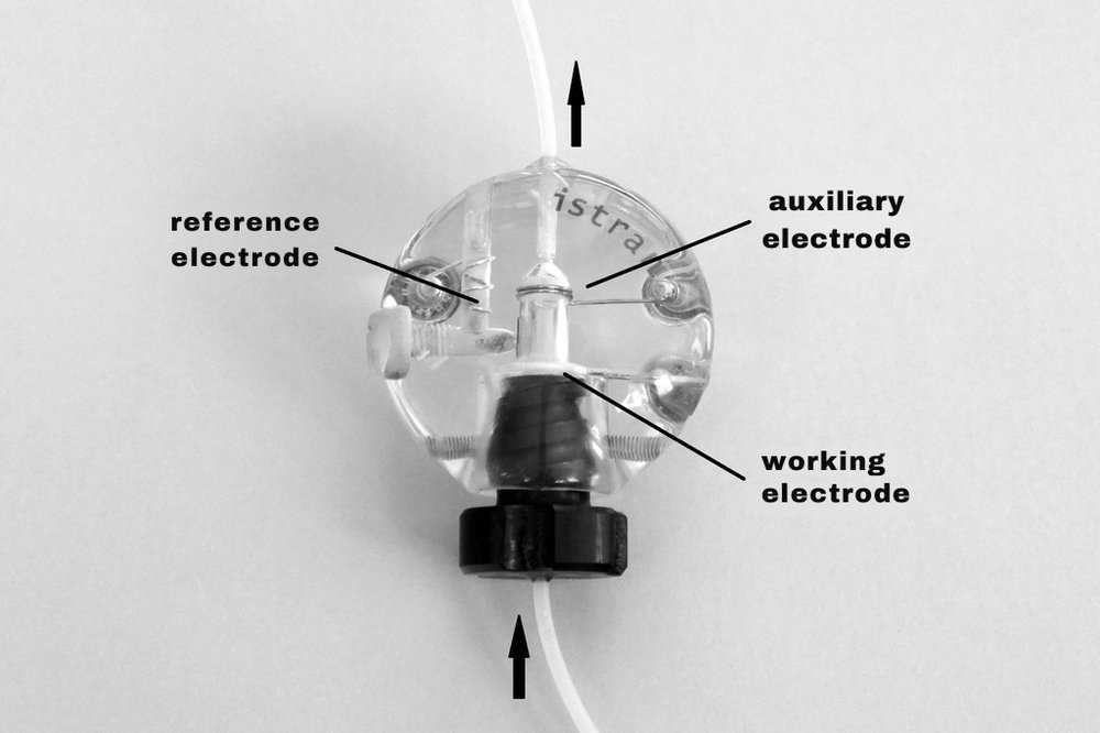
A variety of flow cell designs have been reported [1], but for practical applications, those that are sufficiently robust, have minimal internal volume to reduce solution consumption, and require as little maintenance as possible are preferred. The auxiliary and reference electrodes should also be maintenance-free and integrated into the body of the measuring cell. For the auxiliary electrode, this is straightforward – a platinum wire of suitable dimensions, positioned not too far from the working electrode, is sufficient to avoid the need for excessively high voltages in low-conductivity solutions. In many cases, a pseudo-reference silver electrode is adequate; it is essentially maintenance-free but requires a constant concentration or a reproducible addition of chloride ions to the measured solutions.
A more universal solution is to incorporate a true silver/silver chloride reference electrode into the flow cell. However, this type requires occasional replenishment with KCl solution, and the porous frit can be a source of contamination. Reference electrodes with solid electrolytes are therefore a promising alternative, as they can be custom-fabricated and require no maintenance. In all cases, the reference electrode should be placed as close as possible to the working electrode to minimize the potential drop between them.
Another general rule is that the auxiliary and reference electrodes should be positioned so that the solution flows from the working electrode toward them. This arrangement hydrodynamically separates the working electrode from the other electrodes, preventing contamination from the reference electrode and from reaction products generated at the auxiliary electrode. A technical design of such a cell is shown in Fig. 1.
Electrodes
Working electrodes are the most sensitive components of any electrochemical analyzer because they are in direct contact with the sample. They are thus exposed to the chemical and physical effects of the often aggressive and complex sample matrices, and the flow of liquid across or around the electrode surface can cause mechanical stress.
Since one of the main advantages of flow systems is simple operation with minimal maintenance, electrodes requiring frequent manual cleaning, regeneration, or other surface treatments are unsuitable. For this reason, paste electrodes, although they have excellent electrochemical properties, are problematic. The hanging drop electrode [2] is also unstable under flow conditions, particularly when placed in a narrow channel where the flowing solution can easily detach the drop.
Consequently, the most suitable are solid electrodes with a long service life that do not require frequent mechanical, physical, or chemical surface modification. The most commonly used are carbon-based electrodes, especially glassy carbon, followed by gold, platinum, and silver. Mercury as an electrode material has, perhaps undeservedly, fallen into disfavor and is now used only rarely.
Composite electrodes are also of interest; these can be made from carbon particles or microfibers of various inert conductors bound together with a suitable polymer adhesive, such as epoxy, into a compact, nonporous electrode material. In many cases, such electrodes exhibit the properties of microelectrode arrays, resulting in excellent signal-to-background ratios. Carbon-based electrodes can also be surface-modified, for example, coated with a thin layer of mercury, gold, or polymers to discriminate against certain interfering substances. Gold and silver electrodes can be amalgamated, providing electrochemical properties similar to those of mercury electrodes, but with negligible toxicity (as evidenced by their widespread use in dental fillings).
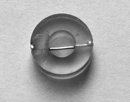
The geometry of the electrode is adapted to the design of the measuring cell and the desired electrochemical efficiency, i.e., the proportion of electrochemically transformed analyte in the total sample volume that has passed through. The highest electrochemical efficiencies, up to 100%, are achieved with thin-layer electrode geometries, followed by disk electrodes in a wall-jet configuration, with efficiencies up to 1%. Planar, tubular, and cylindrical (wire) electrodes (Fig. 2), in which the layer of solution is much thicker than the diffusion layer (0.01–0.1 mm), exhibit the lowest efficiencies, usually up to 0.1%. These efficiencies, however, also depend on hydrodynamic conditions, particularly the linear flow rate of the solution at the electrode surface and the electrode’s surface area.
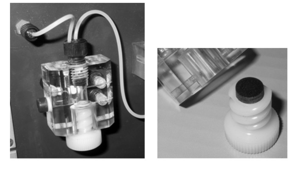
The best signal-to-background ratios can therefore be achieved with configurations that provide the highest possible electrochemical efficiencies and the smallest electrode areas. Cells with a disk electrode composed of a microelectrode array, washed by a sample solution flowing perpendicularly from a capillary (wall-jet cell configuration), come closest to this. The only disadvantage is the potential clogging of the capillary with solid particles, which can be problematic in industrial applications. A technical design of a wall-jet cell is shown in Fig. 3.
Thin-layer electrodes represent systems in which the thickness of the solution layer at the electrode is physically limited to the thickness of the diffusion layer, so that the electrode process is no longer diffusion-controlled but are controlled only by the electrode process itself. Advantages include a high rate of electrolysis, a physically defined volume of solution, and the possibility of carrying out reverse electrochemical processes (oxidation–reduction) without limitation. Technically, such systems can be implemented in several ways.
The earliest was a sandwich arrangement in which the analyzed solution was confined between a flat working electrode and a parallel flat wall at a distance of several tens of micrometers [3]. The measuring cell is detachable, which also allows for cleaning of the electrode. The challenge lies in the proper placement of the reference and auxiliary electrodes.
Another possibility is to place a cylindrical electrode concentrically inside a cylindrical cavity so that the distance between the electrode surface and the inner wall is only 0.1 mm or less. The active electrode area is 6-7 mm² and the volume of solution surrounding the electrode is only 2-4 mm³ (μl). This so-called encapsulated electrode also exhibits the properties of thin-layer electrodes and, due to the favorable ratio of electrode surface area to the volume of the electrolyzed solution, is well suited for coulometric analyses. Its construction is, however, technically demanding.
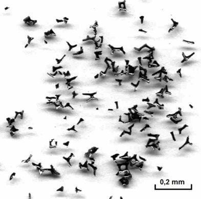
A third and simplest thin-layer electrode type is a porous electrode made from a conductive material with pore dimensions comparable to the thickness of the diffusion layer. This material is most often glassy carbon. The simplest construction uses small carbon particles, preferably crushed glassy carbon (Fig. 4), pressed between two frit layers with contact to the carbon particles [4]. The solution flows through the frit and irregular pores between the particles, where electrolysis occurs. The size of the pores is determined by the size of the carbon particles, typically 5–20 μm (microporous electrode). The total surface area of such an electrode can be 20–50 cm², with a pore volume of 10–40 μl. Since essentially the entire analyzed solution is within the diffusion layer, the electrolysis rate is very high (with a duration on the order of seconds or less), enabling complete electrochemical conversion even under flow conditions. A disadvantage, resulting from the large electrode surface area, is a high background, leading to a lower signal-to-background ratio, and the risk of clogging with solid or colloidal particles.
Porous electrodes can also be made from Reticulated Vitreous Carbon (RVC) (Fig. 5), used for electrochemical synthesis, wastewater treatment, and sound insulation. RVC is available with pore sizes from 0.02 to 2 mm, allowing fabrication of suitable electrodes (macroporous electrodes). Due to their larger pore size, the electrochemical efficiency in flowing solutions is lower than for microporous electrodes, typically 5–50% depending on hydrodynamic conditions. In static solutions, complete conversion is achievable, but over a much longer time than in microporous electrodes.
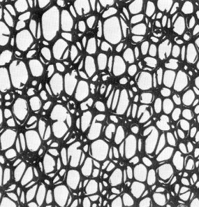
It is related to the smaller electrode surface area (10–15 cm²) and the larger volume of solution within the electrode pores (100–300 μl). Because of their larger pores, small and colloidal particles do not clog these electrodes, which is a significant advantage, especially in industrial applications.
Electrolytes
For voltammetric and chronopotentiometric measurements, the solutions must be sufficiently conductive, except in experiments with microelectrodes. In addition to achieving the required ionic strength, it is often necessary to adjust the pH or add reagents to increase measurement selectivity. Reagents used for these purposes should be readily available, inexpensive, sufficiently pure, non-toxic, and environmentally compatible. Suitable examples include inorganic salts such as sodium chloride and sodium sulfate; acids such as hydrochloric, sulfuric, and nitric; and bases such as sodium hydroxide and ammonium hydroxide. For pH adjustment, acetate, phosphate, and borate buffer solutions are commonly used.
Because flow systems and flow electrochemical cells are sensitive to bubbles, small amounts of surfactants or ethanol are often added to assist bubble removal. However, these additives may interfere with some measurements and cannot always be used. Bubble formation can also be reduced by preparing solutions with freshly boiled water.
References
- Štulík K., Pacáková V., Electroanalytical Measurements in Flowing Liquids. Horwood, Chichester, 1987.
- de Carvalho L.M., Schwedt G., Henze G., Sander S., Analyst, 124, 1803–1809 (1999).
- Bard A.L., Faulkner L.R., Electrochemical Methods. Chapter 10.6, Wiley, New York, 1980.
- Beinrohr E., Németh M., Tschöpel P., Tölg G., Fresenius J. Anal. Chem., 343, 566 (1992).